Home
The 2017 University of Bristol ARM hackathon
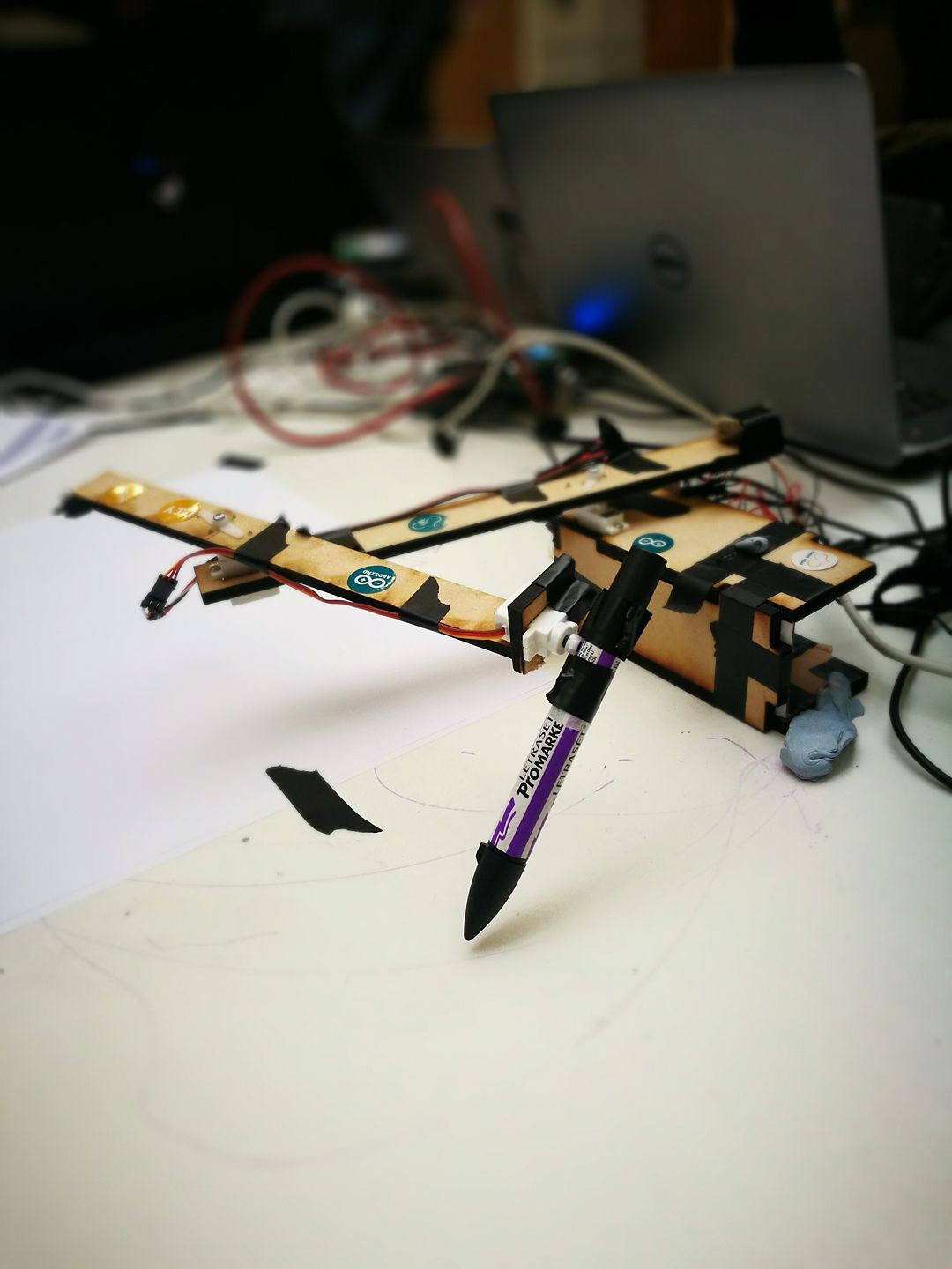
Last weekend 4 friends of mine and I took part in the 2017 edition of the ARM hackathon, organised by the Bristol Electrical and Electronic Engineering Society (BEEES) and sponsored by ARM. They provided us with the hardware (a choice between an Arduino M0 and a Raspberry Pi 3), and we had 24 hours to build something cool. Our team was called The Signature Stealers. We made a two-hinged arm that could draw arbitrary shapes and text using 3 servos (base, arm, pen), some laser-cut plywood, an (actual) rock, Python, C, and Processing. Here’s the lovely beast:
We had 2 mechanical engineers on our team working on the base mechanism, while 3 programmers worked on the various bits and pieces. In the end, we had quite a bit of software:
- a Python HTTP server
- a drawing application written in Processing
- a font renderer done in Python
I mostly worked on the Python server.
The Python webserver or, the bit that did all the maths
The tricky bit was translating the XY coordinates into angles for the two servos. I wanted to find a nice mathematical solution but the other team mate helping with this wanted to just get the intuition and “find something that works”. Whatever, he won in the end. We visualised the possible configurations for the two servos and convinced ourselves that we can define a rectangle in which all the points are reachable. We ended up writing a brute-force solution. We swept the angle of the first circle, calculating the position of each point on its circumference. This became the centre of the second circle (a potential solution). Then, we used the circle equation (the only bit of maths that was coded for hours) to check if the target point was close to the circumference of the second circle. The output looked fine and we went on to write other parts of the program. Only around 4 AM did we realise that we had assumed the two hinges had a range of motion of 360°, whereas the servos only did 180°. If we had stepper motors all of this would’ve been solved and we might have been able to get some sleep.
I was close to giving up around 5 AM when we decided to use the internet and found a very useful link from MathWorks1 talking exactly about what we were trying to achieve. Apparently there’s this entire field of mathematics/mechanics called inverse kinematics2 that studies this sort of thing. The solution we ended up using was to define a grid of points reachable by the arm (taking into account the 180° limitation and the 1° resolution). We only used a rectangular section of this point cloud, and remapped the drawing to fit into those coordinate limits. We then iterated through these points and found the one that is closest to the target point.
The issue was that this was truly an ugly solution, and we were performing duplicated computation at each step. That was all we had time and brain power for in that state. During the demo there was a 2-minute lull while we waited for the damn thing to compute the angles, during which we scrambled to find things to say to the jury.
Two days later, after having caught up on sleep slightly, I managed to rewrite it using NumPy3. This made it around 17x faster. However, it turned out that was not the original issue. What really puzzled me for a few hours during and after the competition was the fact that it was waiting to compute all the angle pairs before sending them to the Arduino. The POST handler was supposed to work like this:
for each point
{
    compute angles
    send one pair to the Arduino
}
Instead, it appeared to be doing:
for each point
{
    compute angles
}
send everything to the Arduino
We had put the serial communication code in a different thread from the HTTP server and computation, as it seemed that waiting for a response was freezing the Processing drawing program (admittedly, communication should’ve been done in a different thread). The server and the serial thread were communicating using the Queue library. I was using queue.put() which, for some reason, blocked the serial thread until everything was computed. Using queue.put_nowait() solved the problem, thought I still have no idea why. The Python docs didn’t reveal much.
As I didn’t work much on them, I don’t know the exact implementation details of the other two parts of the project.
The Arduino software was a simple FSM that accepted three possible commands - a/b/c followed by the value to set the respective servo to. The fun bit was the smoothstep interpolation4 that it was doing between servo positions. Remember the rock I mentioned at the start? You can see a very blurry version of it at the end of one of the arm segments. We used it for counterbalance. Initially, we had 2. Swinging the arm around wildly made the servo gears produce an awful screeching noise because of the momentum the rocks were generating. To counteract that (and make it feel cooler), we decided to interpolate between the two position.
The only issue was that the example code was interpolating from a low value to a high value, but didn’t work the other way round. I would normally use maths (my beloved) to figure something out, but we were very tired at this point. A comment my team mate made provided me with the inspiration needed - “we need to reverse time”. We adapted the Arduino example code by reversing the loop and flipping two values, and it worked!
|
|
The Processing app presented you with a surface you could draw on. The points were sampled according to the refresh rate and then sent via POST request to the server. We had a touchscreen laptop with us, which added that extra bit of spice to our presentation (one of the judges reluctantly provided their signature - thought it looked fake - for replication). It could save a drawing and recall it by pressing ‘a’ (for ARM!). Processing was also great for visualising the problem space and potential solutions. A few days after the hackathon we realised we had got the aspect ratio of the drawing area wrong, which is why everything was weirdly stretched along one axis.
The other set of Python scripts dwarfed the server and the Processing code, and generated bitmaps from fonts. Afterwards, it would produce the point trail needed to draw letters out based on an input string. We thought we would support multiple fonts, but the low resolution and the conversion process meant it only saved us the effort of drawing out all the alphanumeric characters by hand.
I’ve cleaned the server code up a bit and posted it on GitHub5. Once the rest of the code is in reasonable condition, I’ll link the other repositories. Future employers, I apologise for this, but it was written in 24 hours with little sleep (I did end up sleeping - for an hour, on the lobby couches, wrapped in my winter jacket).
We won an honorary mention for being so close to giving up but actually managing to make something work! I guess this could mean the judges thought we couldn’t pull it off and we just surprised them.
A week after the hackathon we were invited to demo the arm at Digimakers6, which is a really cool series of events and workshops that try to attract people aged 7-17 to computing and electronics. I would’ve absolutely loved the thing as a kid. Really cool stuff. Of course, we were struck by, as my very pessimistic friend put it, The Demo Curse. Of course, the arm stopped working properly, so we spent most of the time trying to fix it and showing kids how the thing messes up all their drawings. We went through the code, checking all the different algorithms and interfaces, and we’re pretty sure it’s all correct now. The issues was probably the very cheap servos and the structural unsoundness of the arm itself. We manged to produce a cool visualisation, though.
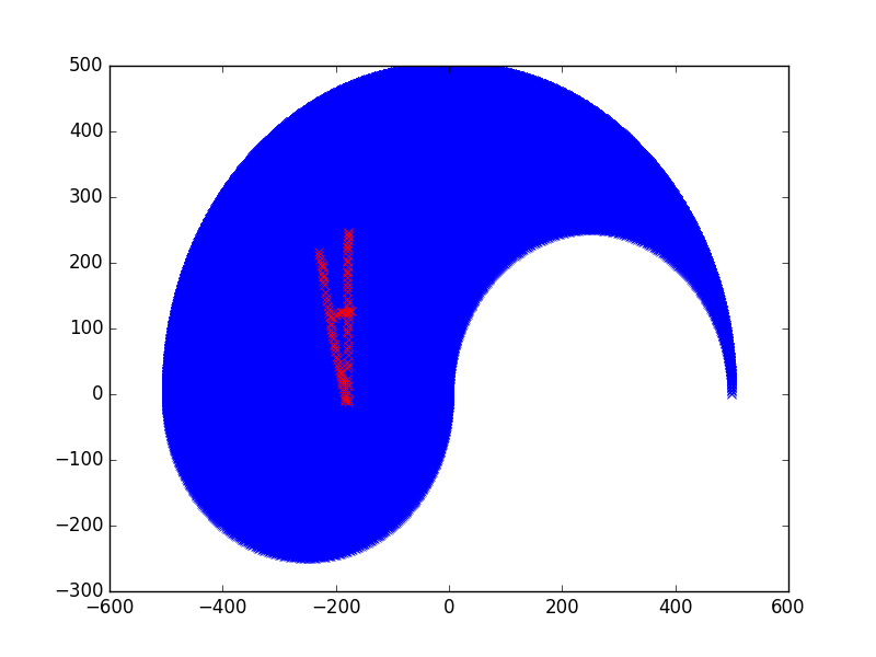
The blue bits are the points we can actually reach. The upside-down A was what we drew in the Processing app and sent to the server. This was done to "prove" that the drawing area only contained reachable points.