Home
An analog stereo to 5.1 upmixer of sorts
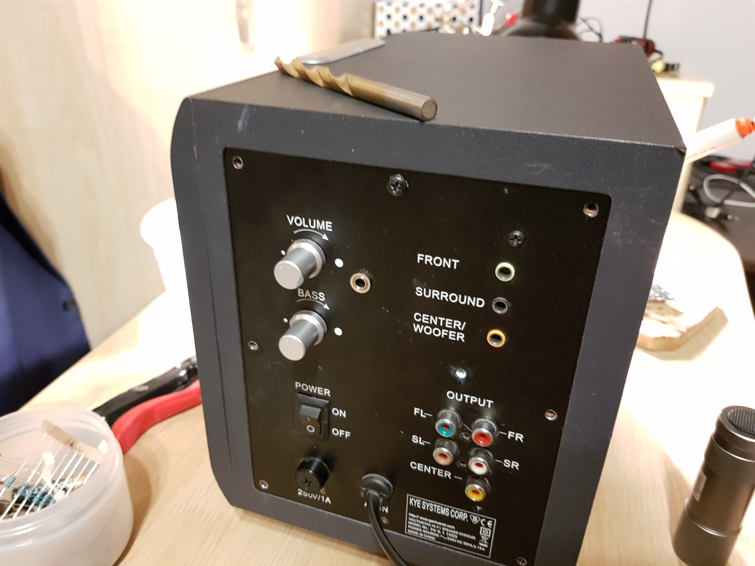
I’ve had this cheapo 5.1 desktop audio system for ages now. To my non-audiophile ears, it sounds okay. However, it’s got one huge flaw - the only input method is 5.1 input from a PC (the green, black, and orange one); it doesn’t have any stereo inputs and it doesn’t perform any upmixing internally. When I wanted to play music off my phone, I’d plug it into the orange input. This would get me bass of some description, and essentially mono audio out of the centre speaker. Many years ago I had attempted to solder a 3-way splitter, but recently I decided to do a proper job. This was my first time designing any analog audio circuit, and I was very pleased with the results!
The main benefit compared to just splitting the signal 3 ways is buffering the input so the device playing the audio is not loaded down too much (resulting in quiet sound). My circuit is heavily inspired by Stack Exchange1. It might be overkill - it buffers the output of the first buffer when splitting it - but, hey, I said I wanted to do a proper job of this!
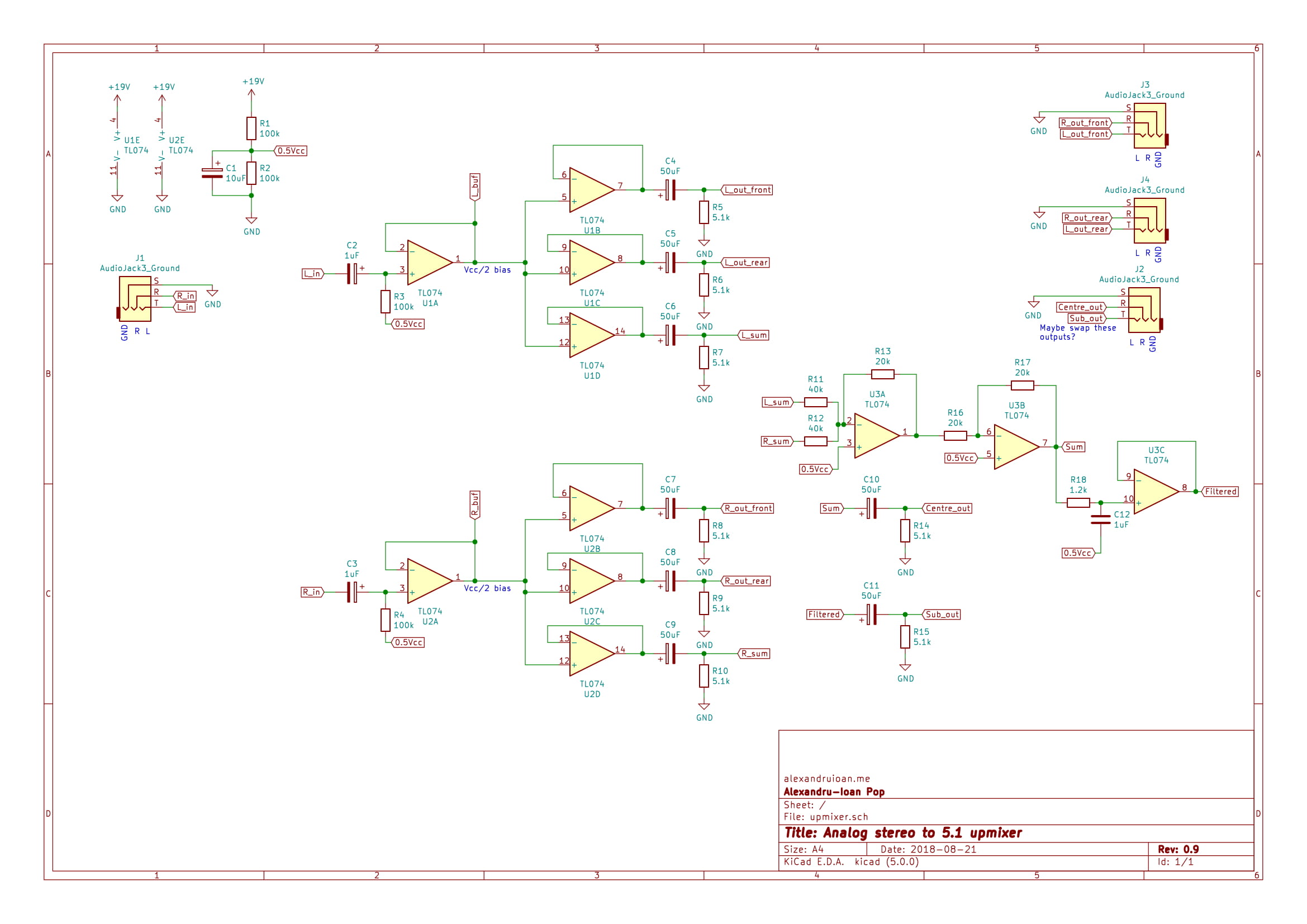
As the Stack Exchange post explains, the signal rides on Vcc/2 produced by the voltage divider. This is needed because the circuit was designed to run off of a single power rail (Vcc and GND), instead of the split rail that opamp circuits often use. This DC components had to be removed at the output, hence the caps.
For centre and subwoofer, I added the left and right channels using a summing amplifier configuration. I’m not sure what this does for stereo imaging and all that, or if I should’ve subtracted them, but it seems to work well enough. Looking back, I should’ve halved the value of the feedback resistor so the output would be (L+R)/2. Right now, the centre channel is a tad too loud (up to twice as loud as left/right) - same for the sub.
As the summing amplifier is inverting, I added a negative buffer (an inverting amp with a gain of 1) to keep the same phase as the other channels. Apparently inverted channels might work better given some room acoustics, but I decided to play it safe.
I added a simple RC low-pass filter for the sub output. I’m not sure how happy the sub is if you feed it high frequencies (it might “overheat and fail if a very strong HF signal is sent to it for a long enough duration”2). The 1.2k resistor and 1uF cap yield a cut-off frequency of about 132Hz. It turns out all those nice equations only work if what’s downstream from the LPF has infinitely high impedance (or an open circuit). My headphones/sub do not have infinite impedance, so I spent some time wondering why the hell it sounded like my LPF was just attenuating all sounds and not filtering anything. A buffer on its output fixed the issue - the buffer amplifier has very high input impedance.
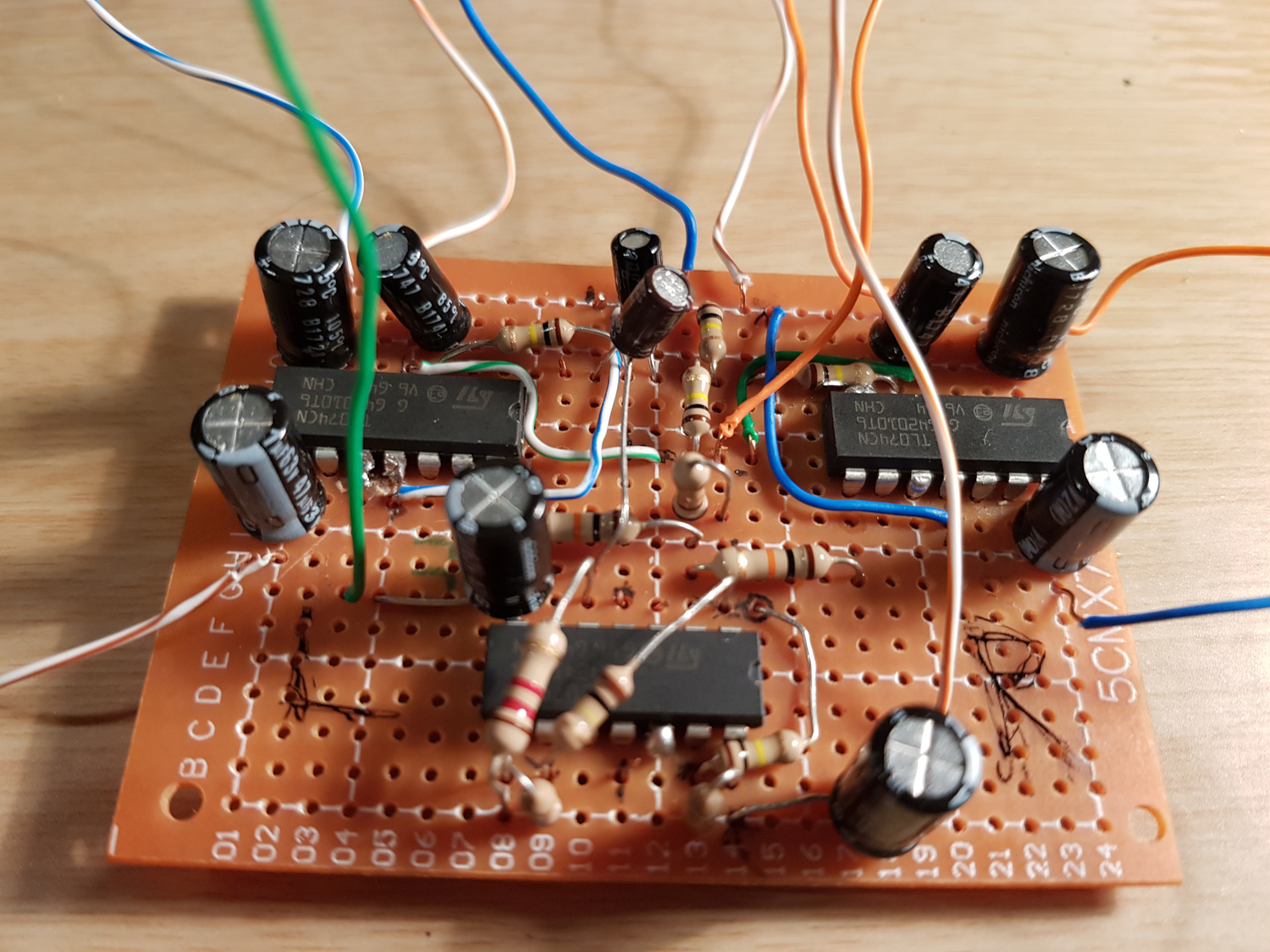
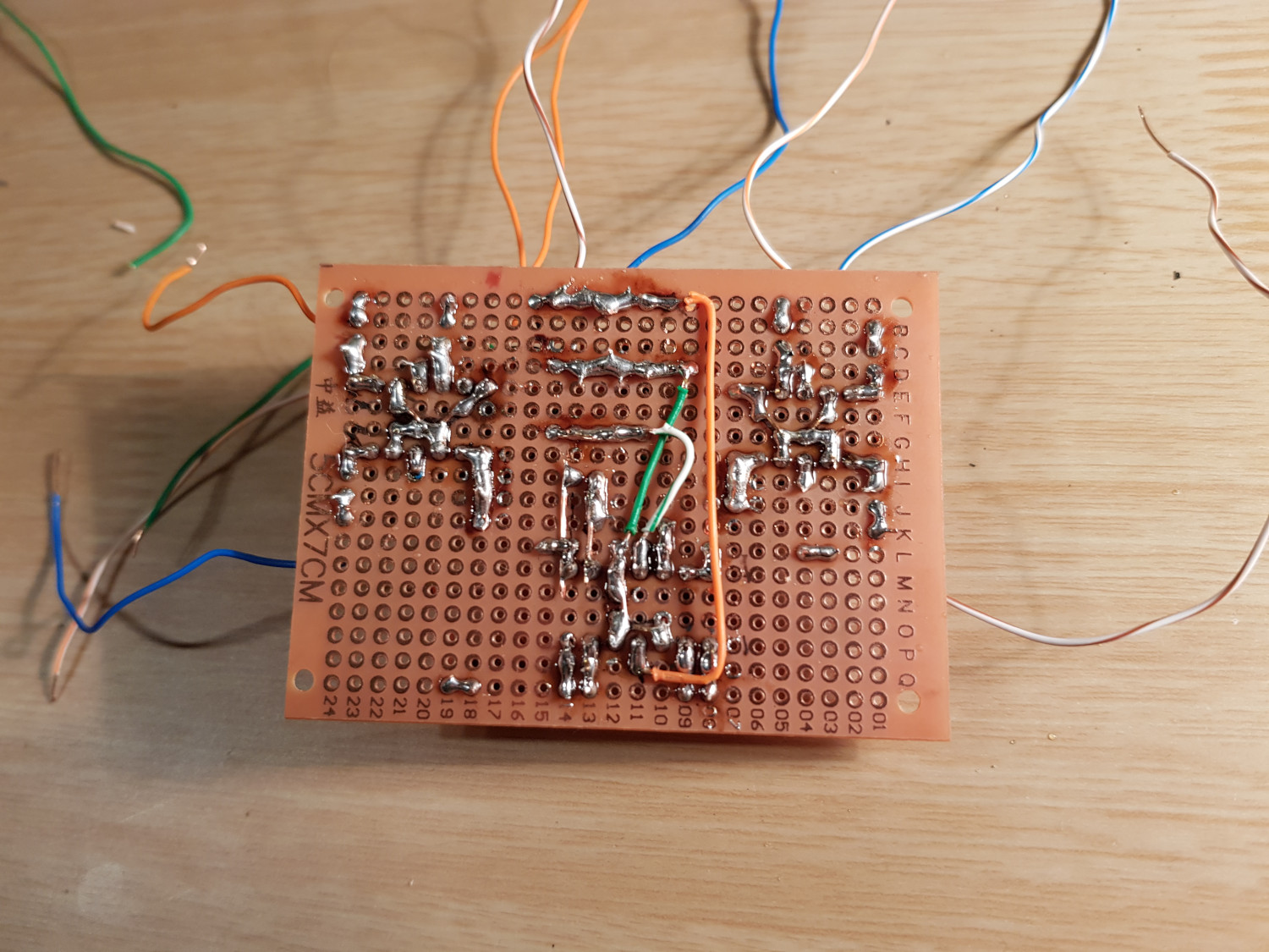
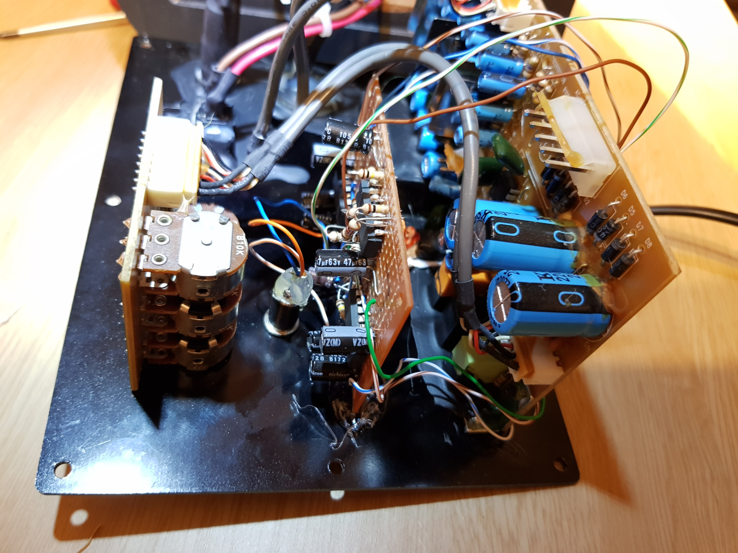
Once everything was working, it was time to move to perfboard. I used up a lot of solder, but it allowed me to make some very neat connections underneath the ICs (hover over the image to zoom in).
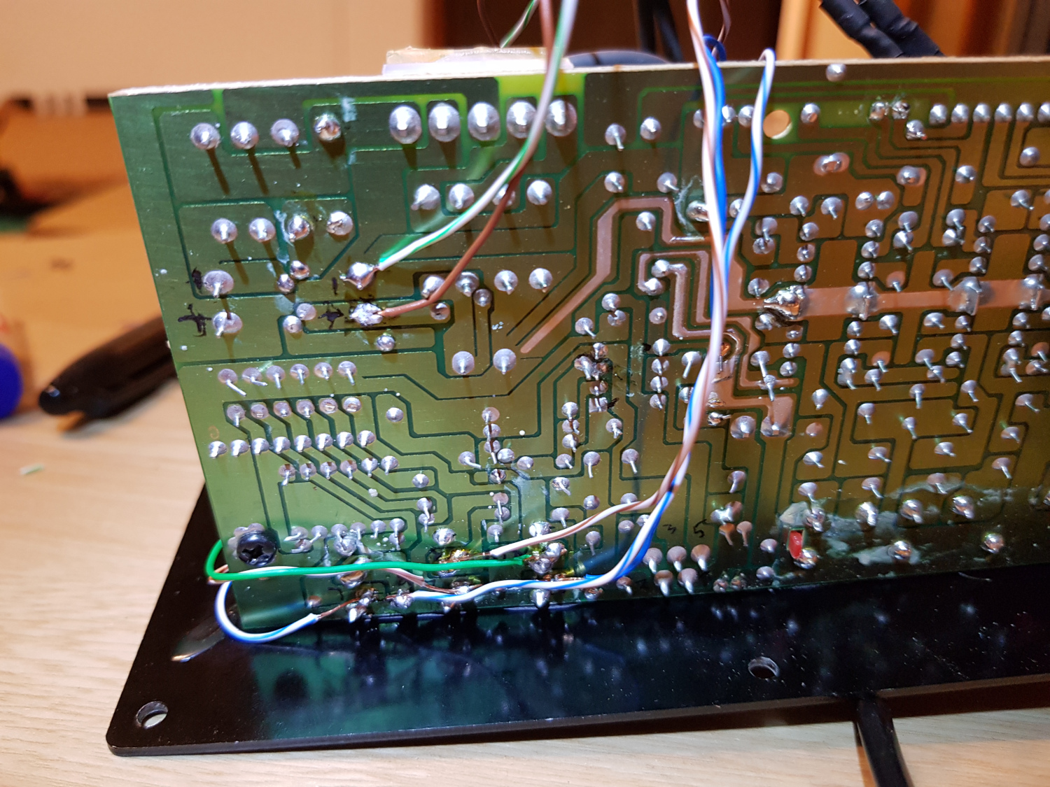
While I was prototyping the circuit on the breadboard, I used a 9V battery. The plan was to mount all of this inside the subwoofer, so I had to find some suitable power rail in there. I opened up the sub and I spotted an amplifier IC (a-ha!). Unfortunately, it ran off of +- 19V, and the maximum input voltage my TL074s would accept was 36V. With help from a friend, I managed to navigate the rectifier part of the original PCB and identify a single 19V rail, which was perfect. I cautiously tested it on a small circuit on the breadboard, and nothing blew up! I identified the connection points of the original inputs on the PCB and wired my outputs to those, careful not to mix up left and right. I hot glued the perfboard in place, and it fits in perfectly with the rest of the stuff in there.
Dad and I drilled a hole and mounted the input panel-mount jack. You can barely tell that it’s a mod; I’m really happy with that. I used it for a while now and it’s been working very well.
Here are the Kicad schematic files.